Technology
Film Sense Multi-Wavelength Ellipsometry Technology
What is Ellipsometry
Advantages of Ellipsometry
Multi-Wavelength Technology
Software
What Is
Ellipsometry?
Ellipsometry measures the change in polarization state of reflected light
Film Sense ellipsometers use polarized light to non-destructively characterize samples. In an ellipsometer system, the Source emits light with a known polarization, which is obliquely incident on the sample, and the Detector measures the polarization state of the light reflected from the sample. See the video for a 3D visualization of the reflection of polarized light from a sample.
The change in polarization state caused by the sample reflection can be defined by the ratio of the sample reflectivity for p-polarized light (Rp), over the sample reflectivity for s-polarized light (Rs). This ratio is a complex number, which is typically denoted by ρ (rho), and is often reported in terms of the ellipsometric parameters Ψ (Psi) and Δ (Delta), as defined by the following equation. According to this equation, tan(Ψ) defines the magnitude of the reflectivity ratio for p- and s- polarized light, and Δ defines the phase difference between the reflected p- and s- polarized light.
An alternate representation of the ellipsometric parameters is shown below. The N, C, and S ellipsometric parameters can be calculated in terms of the Ψ (Psi) and Δ (Delta) parameters, assuming the sample is isotropic and non-depolarizing. One of the advantages of the N,C,S representation of the ellipsometric parameters is that if the sample is depolarizing, the degree of polarization P can also be reported.
The ellipsometric parameters measured on the sample (and reported in either the Ψ/Δ or N,C,S representation) can be further analyzed to determine sample properties of interest, such as film thicknesses and optical constants.
Advantages of
Ellipsometry
Ellipsometry is highly sensitive to very thin films
Ellipsometry is Highly Sensitive
The most well known advantage of ellipsometry is its extreme sensitivity to very thin films. This advantage derives from the ellipsometric Δ (Delta) parameter, which is a phase quantity. By measuring the phase between p- and s-polarized reflected beams, ellipsometry provides precise determination of film thickness, down to sub-monolayer film thicknesses, even though the wavelength of the measuring beam (≈ 500 nm) is very long compared to the film thickness (which can be < 0.1 nm). With Film Sense Multi-Wavelength Ellipsometers, thickness precisions of better than 0.0004 nm can be achieved on a wide range of samples, ranging in thickness from 0 to 5000 nm.
Increased Information Content
When compared to a simple sample reflectivity measurement (which just measures the intensity of light reflected from a sample), the ellipsometric measurement (which utilizes polarized light) is certainly more complex. However, the complexities of the ellipsometric measurement can be offset by the additional information contained in the ellipsometric parameters: 2 ellipsometric values are measured at each wavelength (and the degree of polarization P can provide a 3rd value), while reflectivity only measures 1 value.
Direct Determination of Substrate Optical Constants
An example which directly utilizes the information content in the 2 ellipsometric parameters Ψ (Psi) and Δ (Delta) is the calculation of the pseudo-dielectric function <ε> of a substrate. The dielectric function ε is one way of characterizing the optical properties of a material, and it is a complex value, with a real part ε1, and an imaginary part ε2. The dielectric function is also the square of the complex index of refraction ñ(the real part of ñ is the index of refraction n, and the imaginary part of ñ is the extinction coefficient k). Assuming the measured sample is a substrate with no overlayers or roughness, the pseudo-dielectric function for the substrate <ε>can be calculated from the ellipsometrically measured Ψ (Psi) and Δ (Delta) values, using the formula below (the parameter θ is the angle of incidence of the measurement beam). Since the preceding assumptions are not always rigorously satisfied, the prefix of “pseudo-” is applied, as denoted by the <brackets>.
Obtaining the real and imaginary parts of the dielectric function of a substrate (or equivalently, n and k for the substrate) from reflectivity data would require measurements over a wide spectral range, combined with data analysis with an appropriate dispersion model. With ellipsometric data, the dielectric function (or equivalently, n and k) for a substrate can be directly calculated.
Determination of Film Thickness and Index of Refraction
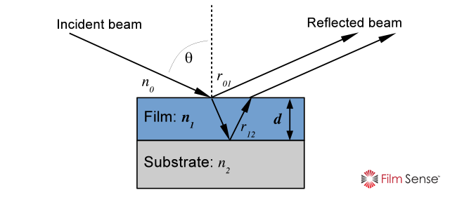
Another example which demonstrates the information content advantage of ellipsometry is the determination of the thickness and index of refraction of a transparent thin film on a substrate. Since ellipsometry measures 2 parameters, Ψ (Psi) and Δ (Delta), it is possible to directly determine 2 sample related parameters, which in this case are the thickness of the film d, and index of refraction n1 of the film. This is done by numerically inverting the thin film interference equation shown below. In this equation, the reflection coefficients rp,s at each interface and the film phase factor β are calculated using the index of refraction for each media, the angle of incidence θ, the Fresnel equations, and Snell’s law (the Film Sense software handles all these calculations internally).
While there are some limitations in this analysis for very thin films less than 10 nm in thickness (due to correlation between the film thickness and index), ellipsometry is superior to reflectometry when determining the index of refraction of films less than 25 nm in thickness.
Another limitation arises if the film thickness determination is done with a traditional single wavelength ellipsometer: multiple thickness values can satisfy the thin film equation, leading to a thickness “periodicity” problem. With Film Sense Multi-Wavelength Ellipsometers, the thickness periodicity problem is eliminated by the multiple measurement wavelengths.
Ellipsometry is Intensity Independent
As an optical technique, ellipsometry is fast and non-destructive, and can be performed in a wide range of environments: in the lab, on a factory floor, in a vacuum chamber, or even with a liquid ambient. A unique advantage of ellipsometry is that the measured parameters are not dependent on the intensity of the measurement beam. This advantage comes from the definition of the ellipsometric parameters by a ratio. The beam intensity independent property of the ellipsometric measurement can be very beneficial in situations where maintaining constant beam intensity would be challenging, such as in situ measurements, or long term measurements requiring high stability. Ellipsometry is also less susceptible to many types of sample non-idealities, such as scratches, dust, defects, and macroscopic roughness. These types of sample non-idealities scatter the measurement beam, such that light scattered from these non-idealities does not enter the ellipsometer’s Polarization State Detector (which collects only the ideal, specularly reflected light from the sample).
Film Sense Ellipsometer
Multi-Wavelength Technology
Innovative and Powerful
Since ellipsometry uses polarized light, an ellipsometer system is typically a complex and expensive optical instrument. However, Film Sense Multi-Wavelength Ellipsometers hide the complexity from the user, packaging powerful multi-wavelength ellipsometer technology into a compact, robust, and affordable instrument, and enabling quick and accurate ellipsometric measurements. With Film Sense Ellipsometers, you do not need to understand the details of how the ellipsometric measurement is made, and operating the instrument is simple. Some of the innovative features which are incorporated into Film Sense Ellipsometers are described below.
Light Source
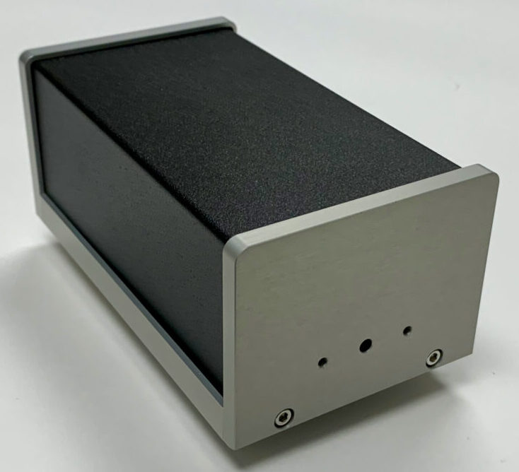
The Film Sense Light Source Unit provides the Polarization State Generator for the ellipsometer system. 4 or 8 visible Light Emitting Diodes LED’s are used as light sources. LED’s are an ideal light source for an ellipsometer system. The only down side to using LED’s as a light source is their wide spectral bandwidth, but this is accurately and automatically corrected for in the Film Sense data analysis procedure*. Since they have long lifetimes (>50,000 hours), the Film Sense LED’s never need to be replaced or realigned over the lifetime of the instrument. In operation, the LED’s are sequentially scanned in less than 20 ms to provide ellipsometric data at 4 or 8 wavelengths essentially simultaneously. The internal optics of the Film Sense Light Source Unit* combine the light from the LED’s into a common beam, which is bright and uniform. The Film Sense Light Source Unit also includes a Polarizer, which sets the polarization state of the beam that will be reflected from the sample.
Film Sense 3rd and 4th generation ellipsometers incorporate a hollow shaft motor to provide system control of the Polarizer rotation angle (gen. 1 and 2 systems used a manual rotation mechanism). To calibrate the orientation of the Source and Detector units with respect to the sample, the Polarizer is automatically rotated to 8 positions. This simple calibration procedure takes only a few seconds, and only needs to be done when the Source and Detector units are mounted on a process chamber for in situ measurements, or when the Source and Detector units are remounted to the ex situ measurement Frame. The motorized polarizer also enables zone averaged measurements, in which the ellipsometric data is averaged from measurements acquired with the polarizer at the +45º and -45º orientations. Zone averaged measurements can cancel many systematic measurement errors, such as sample mis-alignments in the plane of incidence, and one component of vacuum window birefringence (both of which effects are common with in situ measurements).
Detector
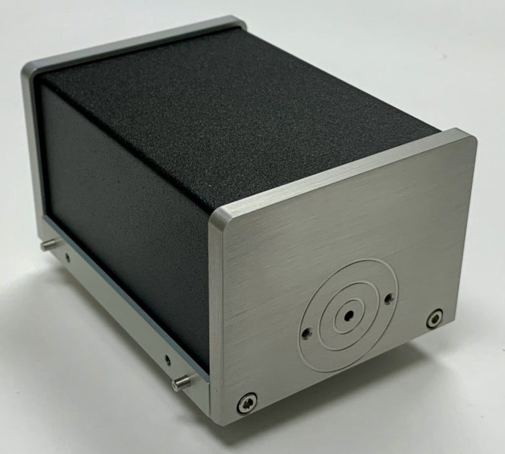
The Film Sense Detector Unit provides the Polarization State Detector for the ellipsometer system. The Film Sense Detector design has no moving parts, and is based on the Division of Amplitudes Polarimeter (DOAP) concept first proposed by Azzam (‘‘Division-of-amplitude photopolarimeter (DOAP) for the simultaneous measurement of all four Stokes parameters of light’’, R. M. A. Azzam, Opt. Acta Vol. 29, page 685, 1982). One disadvantage of the traditional DOAP design is that the polarization measurement accuracy can be affected by the alignment and uniformity of the incoming beam. To overcome this disadvantage, the Film Sense Detector implements a novel optical configuration* to cancel measurement errors caused by mis-alignment or uniformity of the measurement beam. Since there are no moving parts, the ellipsometric data can be acquired very quickly (1.7 ms minimum acquisition time for 1 wavelength of data, with Fast Mode), and long term measurement stability and robustness is also improved. The computer which controls the data acquisition and performs the data analysis is also integrated into the Film Sense Detector Unit, resulting in a compact sensor that requires no additional control electronics.
Ex Situ Ellipsometry Measurement Frame
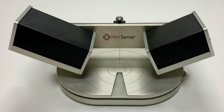
For typical measurements, the Film Sense Light Source and Detector units are mounted on the standard frame. This frame can accommodate samples up to 200 mm in diameter, up to 23 mm in thickness, and it provides manual height adjustment for the sensor units with respect to the sample surface. Custom attachments can be added to the frame, and the Light Source and Detector units can be attached to a custom frame (contact us for CAD drawings for custom interfacing or OEM applications). Standard options for in situ mounting, focusing, and more, are also available (see Products page).
Film Sense
Software
Powerful ellipsometry data analysis software that is easy to use


